
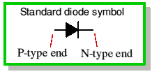
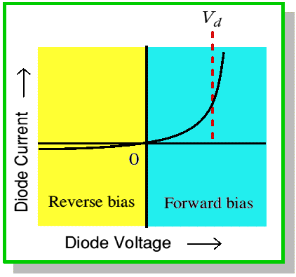
Unlike a resistor, the amount of current through a diode will
depend upon 'which way round' we apply the voltage.
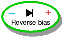
When the voltage is applied this way round it tends to pull the
free electrons and holes apart, and increases the height of the energy barrier
between the two sides of the diode. As a result it is almost impossible for any
electrons or holes to cross the depletion zone and the diode current produced is
virtually zero. A few lucky electrons and holes may happen to pick up a lot of
thermal (kinetic) energy. This gives them enough 'go' to cross the barrier,
hence the reversed biassed current is not zero, just very, very small.
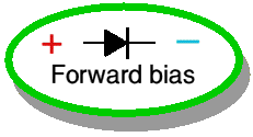
When the voltage is applied this way round it tends to push the
electrons and holes towards the junction. It also reduces the height of the
energy barrier and reduces the width of the depletion zone. These effects make
it easier for free electrons and holes with modest amounts of thermal (kinetic)
energy to cross the junction. As a result, we get a sizeable current through the
diode when we apply a forward bias voltage.
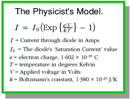 If you look up diodes in a physics book you'll probably find an
explanation which finishes up telling you that current through a diode varies
exponentially with the applied voltage. The shape of this exponential curve
depends upon various factors which include a 'fiddle factor' called the
saturation current.
There are two problems with this
result. One is that the equation is fairly complicated and quite difficult to
use for analysing some circuits. The second problem is that this equation is
usually wrong! The reason for this is that the actual current/voltage
relationship depends upon the detail of how the diode was made - the choice of
materials, doping, etc. Being simple souls who like a quiet life, electronic
engineers deal with these problems by simplifying things and using whichever of
the following three models of the diode suits them.
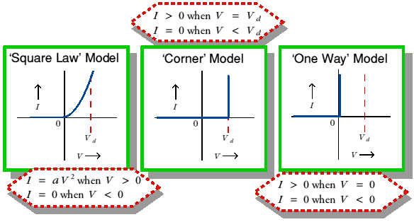
Vd represents the height of the diode barrier
when no voltage is applied. This means that the energy required for an electron
(or hole) to be able to cross the barrier is eVd.
 The 'square law' model assumes that the current, when forward
biassed, is proportional to the square of the applied voltage.
 The 'corner' model assumes that the current is zero for any
voltage below Vd but rises when we try to apply a voltage
greater than this. In effect, the diode is viewed as a sort of 'switch' which
is open when we apply low or negative voltages but which closes when we try to
apply a voltage equal to or greater than Vd. This means that
it is impossible to get a voltage larger than this across the diode. If we try
to apply a larger voltage one of two things happen; either the voltage source
gives all the current it can manage and the diode current sits at this value,
or the current is so high that the power warming the diode (= voltage x
current) blows it up! In this way of looking at things, Vd
is called the corner voltage.
 The 'one way' model simplifies things even more by assuming that
the corner voltage is so small that we can regard it as being zero! Although
this is a drastic simplification, for many practical purposes, it is the only
thing we need to remember about a diode. That is, it behaves like a switch
which is open (no current) when we apply volts on way and closed (as much
current as we like) when we try to apply volts the other way.
Whichever simple model we adopt, the basic diode maxim is therefore:
Forward bias - all current, almost no volts.
Reverse
bias - all volts, almost no current.
Electronics
homepage
Course
contents
 Content and pages maintained by: Jim Lesurf (jcgl@st-and.ac.uk)
using HTMLEdit on a
StrongARM powered RISCOS machine.
University of St. Andrews, St Andrews, Fife
KY16 9SS, Scotland.


 If you look up diodes in a physics book you'll probably find an
explanation which finishes up telling you that current through a diode varies
exponentially with the applied voltage. The shape of this exponential curve
depends upon various factors which include a 'fiddle factor' called the
saturation current.